Example 9
Contents
Example 9#
Detention pond
Objective#
This example is to verify if a particular detention pond can operate effectively under different conditions; in particular
Does the pond overflow with the supplied rainfall input?
What is the maximum constant-intensity, 6-hour storm that the pond can accommodate without activating the overflow spillway?
Situation#
The figure below is a plan view of a rectangular detention pond.
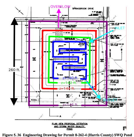
The bottom of the pond is at elevation 139 feet. Several rectangular contour lines are shown. If the pond has one foot of water in storage, the blue line represents the pool elevation, and the volume would be the product of the area enclosed by the blue contour and the depth (1 foot). At depths greater than one foot, the pond sides are sloped and not vertical.
The inlet is a 2-foot diameter culvert that drains a 9-acre light-industrial complex. The invert elevation of this culvert at the pond is 139 feet.
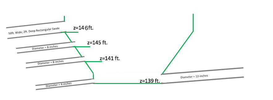
The outlet works is a riser pipe which activates when the stage in the pond is 141 feet. The diameter of the outlet pipe is 8-inches. A secondary outlet pipe, also 8-inches activates at elevation 145 feet.
A small 4-inch drain pipe is at the pond bottom so that the pond drains completely after a storm. If the pond stage exceeds 146 feet, the emergency overflow is a rectangular swale 25 feet wide and 2 feet deep which drains directly into a nearby bayou.
An elevation-view sketch is below that depictsthe inlet-outlet elevation relationships.
Build a SWMM model of the detention pond (Storage Node; Tabular Depth-Area). Assume the catchment that drains to the pond can be represented as a 9-acre square region, with an overland slope of 1.0%. Use an appropriate model for runoff generation, given that the pond will recieve runoff from a high-density residential apartment complex.
The inlet pipe is a 2-foot diameter, 200-foot long RCP, laid on a slope of 0.5%. The outlet pipes and overflow swale are also at slope 0.5%; they are also 200 feet long.
Note
Modeling Decisions The multiple outlets will connect to a common junction node 200 feet from the pond, which, in-turn will then connect to an outfall (see the layout below). The connection to the outfall is a 6-foot diameter conduit, 200 feet long. The outfall is set as a FREE outfall boundary condition.
The contributing catchment is simulated as a 9-acre square area with NRCS Curve Number of 75 (low-ish for an apartment complex).
The SWMM model is then run using a constant intensity of 3-inches per hour for 6 hours. Prepare output plots of pond depth versus time, pond inflow versus time, and pond outflow versus time.
Supporting Data Files#
Simulation Results#
From the supplied drawing, one can import into Adobe Acrobat or similar tool to determine the ponded surface area at different elevations. Use the tools to measure the “big” area in generic “PDF units” (in this case Acrobat measured in sq. inches). For example, the 260 X 260 feet area (in Magenta) is 52.45 in\(^2\) in the software.
Note
Your values will likely be different, the point is the big square is known so the conversion is straightforward.
Thus the 52.45 in\(^2\) = 67,600 ft\(^2\) = 1.55 acres. The conversion to use for a generic measurement is: 1 in\(^2\) = 1288.8 ft\(^2\). The results for the supplied drawing is:
Contour(ft) |
Depth(ft) |
Area(PDF units) |
Area(ft\(^2\)) |
Area(acres) |
|---|---|---|---|---|
147 |
8 |
52.45 |
67,600 |
1.552 |
146 |
7 |
52.45 |
67,600 |
1.552 |
144 |
5 |
24.93 |
32,130 |
0.737 |
142 |
3 |
15.06 |
19,410 |
0.445 |
140 |
1 |
7.35 |
9,743 |
0.223 |
139 |
0 |
0 |
0 |
0 |
A conceptual layout is depicted below
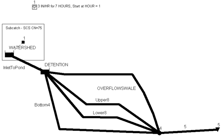
The simulation (using FreeSWMM) is depicted below. The input file is DetentionPondExample.inp already placed in the computing environment.
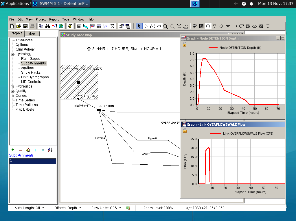
Interpretation#
Investigation of the input file will show the pipe resistance values are really smooth, whereas th watershed overland flow values are such that a lot of water is stored on the watershed. The pond is undersized in this example, as evidenced by the overflow swale activation.
Additional Comments
Increasing the sizes of all the outlets to 1-foot, alleviates the overflow swale activitation.
Introducing another storage element to represent the catchment itself might be useful to help guide the pond sizing.
This is a pretty small area and pond - SWMM is probably overkill for sizing the pond unless it is part of an array of hydraulic features being explored.